
Highlights
Within WP2, three different thrusters at different input power classes has been built and tested. The 300 W version was fired for more than 3000 hours, which a significant improvement compared to other iodine is fed engines and a very important milestone for the global electric propulsion and space community.
Significant Achievements
iFACT has proofed the ability to use iodine as propellant for in-space propulsion by experimentally demonstrating over thousands of hours that an electric engine can be fired. This has been executed at 300 W power level and 13 mN of thrust.
What do you think have been the most important results that have emanated from WP2?
- Very long firing with iodine for multiple thousands of hours
- Demonstration that Iodine and the advanced cusp field thruster can be used at different power classes from 10 W to 1kW
- Proof that iodine can be used as main propulsion propellant for space missions
- Proof that the hardware and the test equipment can scope with potentially reactive environment
- End to End testing of all subsystem components, incl. Thruster, cathode, propellant feeding, and electronics.
The achievements in WP2 that we are you most proud of are the:
- Successful construction and testing of hardware in three different power classes.
- Completion of all tasks almost on schedule despite the demanding external environment.
- More than 3000 hours of recorded operation with iodine.

Highlights
The elaboration of a business plan and market analysis enabled to define short & mid-terms opportunities for the iFACT subsystem implementation. A first version of a subsystem specification has been delivered, based on those opportunities, in order to highlight the technical key requirements of the iFACT subsystem.
Significant Achievements
The most important result that has been achieved is the availability of a specification for the iFACT subsystem which is in line with the most up-to-date market trends, i.e to be in position to bid as soon as possible with an iFACT subsystem with a competitive and disruptive thruster.
The elaboration of a business market analysis enabled to update the iFACT design to be in line with potential future customers’ expectation regarding price target and competitiveness for the mid-term bids.
The WP3 researchers are most proud of contributing to the development of a disruptive Electric Propulsion (EP) system (especially for the I2 propellant) and support the entire team to consolidate the definition of requirements that will pave the way for the iFACT subsystem towards a more industrial product.


Highlights
The development of an Iodine compatible hollow cathode can enable iodine thruster systems to operate with a single propellant, rather than requiring two propellant types that result in increased system complexity and cost. This work package is testing a range of cathode configurations and emitter materials to determine the feasibility of an Iodine compatible thermionic hollow cathode.
Significant Achievements
The University of Southampton (UoS) has been focusing on the design of an Iodine compatible Hollow Cathode (iHC2A). The device has been designed with enhanced modularity for quick parametric changes during the experimental test campaign. The design is shown in Figure 1 below.
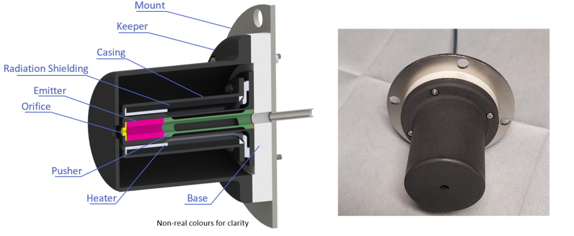
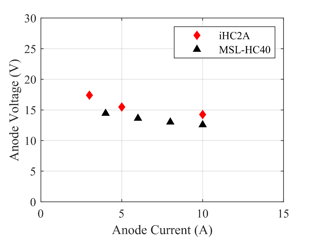
Given the material compatibility issues with iodine, especially at elevated temperatures (>100°C), the cathode is modified compared with conventional cathodes. Critically, the cathode tube material is graphite, instead of the typically employed refractory metal, such as, tantalum or molybdenum. The design also utilizes an iodine compatible graphite heater to raise the emitter to thermionic temperatures. The ceramic base provides thermal isolation to enable attachment to a conventional stainless-steel flange with integrated propellant line. The system is fully modular so that each part can be removed and adapted, in this way various emitter types can be tested, such as C12A7, LaB6 or BaO-W. Furthermore, COMSOL Thermal simulations have been the primary driver in the thermal optimization of the system to ensure the insert temperature is maintained for adequate thermionic emission with minimal power expenditure. The iHC2A has been tested with a LaB6 emitter and found to have comparable performance to commercially available HCs despite the iodine compatibility modifications, as shown in figure 2.
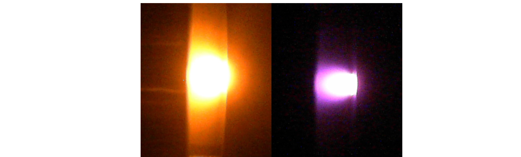
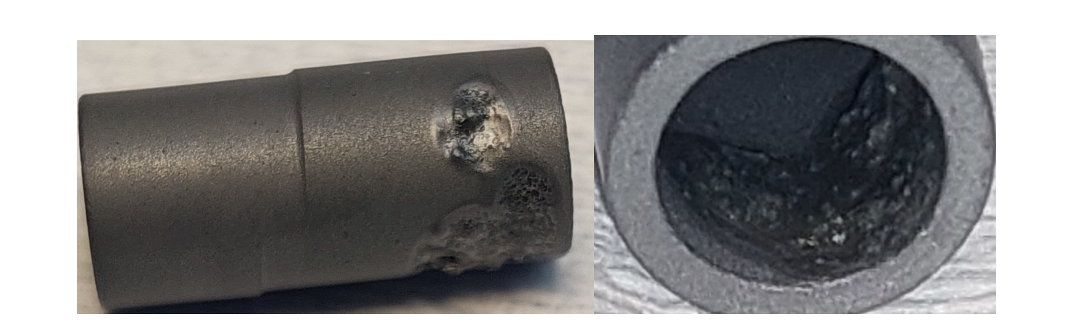
The system has subsequently undergone preliminary tested with an C12A7 emitter. The HC temperature was steadily raised with heater power, with the cathode tip temperature measured in real time via an optical pyrometer inside the vacuum chamber. With a keeper set to Ik = 0.1 A and Vk = 400 V set, ignition occurred at 1230℃ with a flow rate of 20 sccm (Xe). As shown in Figure 3, heater power was steadily reduced with increasing keeper current. Discharge instability occurred with anode current above 0.25 A and testing stopped. The discharge instability occurred was clear with an intensive yellow pulsing glow (see Figure 4) which was suspected to be the cause of, or the result of, emitter melting. The CA12A7 emitter was removed from the cathode to inspect (see Figure 5) with clear localised non-uniform melting seen on the downstream end of the emitter. The localised melting penetrated the thickness of the emitter in several spots. This testing demonstrated the changelings of adapting C12A7 use given that the operating temperatures are very close (~ < 200C) of the materials melting temperature.

The UoS TDHVL VC2 Chamber has been upgraded (see Figure 6) for Iodine use, employing an Edwards STP-iS2207C mag-lev turbo-pump, roughed by an Edwards nXDS20iC scroll-pump with a liquid nitrogen Iodine trap. A sliding door with support allows easy test setup and removal from the system.
This system is to be utilized for the iodine testing; iHC2A phase 1 testing with Xenon will shakedown the new facility by repeating the LaB6 Xe test, which will be followed by iHC2A phase 2 testing with Iodine. Performance sweep testing (0.5-5 A operation) is planned to be conducted with operation testing up to 50 hours to identify failure mechanisms.
Tests conducted at NASA Glenn have suggested that BaO should not be used for Iodine applications due to clogging and unreliable ignition. There have been recent attempts to run BaO cathodes on Iodine, however these have been focused on plasma diagnostics rather than endurance and lifetime issues. There is little to no information regarding LaB6 compatibility, with only brief mentions of tests having taken place. So, this work seeks to determine systematically, what emitter materials can be utilized with iodine for thermionic hollow cathodes.
But what really makes WP4 team proud is the development of the iodine compatible cathode and the chamber test facility which can enable the current and further research and development into iodine hollow cathodes.

Highlights
The thermionic current density as physical value for the electron emission of C12A7:e- ceramic under heating in vacuum was improved from 0.4 to 679 a/m² (@850 °C) by material development. The performance of hollow cathodes made of the optimized C12A7:e- was successfully demonstrated in a thruster.
Significant Achievements
The main goal of WP5 was the development of the electron-emitting ceramic for generating higher current density. The electron-emitting material made of 12CaO.7Al2O3 (called as C12A7) was prepared by melting CaO and Al2O3 in the stoichiometric ratio of 12:7 at a temperature of 1450 °C in a Platinum crucible and quenched on a brass block. The glass was milled, and the resulting powder was shaped by pressing. The C12A7 was densified to a ceramic by sintering the pressed bodies and the electronic state was generated by using a reductive sintering atmosphere. The basic C12A7:e- filled with electrons has a low work function of 2.6 eV and emits electrons in vacuum by heating in an electric field (thermionic current density).
In this project, the current density of C12A7:e- was improved by doping the material with larger ions (Sr, Ba) on the Ca site. Therefore, C12A7:e- with low content of Sr or Ba was prepared and the current density as a function of the temperature was measured by Airbus Fh. The impact of doping was successfully demonstrated by a reduced work function of 1.8 eV and improved current density.
Additionally, the backside contact (heater side) was optimized for low electronic resistance by using different types of metal coatings. Starting with a silver-based metal filler, the development in the project was focused on gold and Ti-Cu-Ni coatings on the backside of the C12A7:e- ceramic. The reduced resistance by using these coatings resulted into higher current densities during heating the C12A7:e-.
Finally, the doped and contacted C12A7:e- indicated improved current density starting with 0.4 A/m² (850 °C) at the beginning of project and ending with 679 A/m² (850 °C) after the material development.
Hollow cathodes were prepared of the optimized material and were tested in a thruster set-up by the University of Southampton.
The low work function of C12A7:e- was known from literature and the idea for enlarging the structure by doping with Sr or Ba for improving the current density was the motivation for this part of the project. After starting this development, a paper was published reporting the doping with Sr in single crystals of C12A7:e- [1]. There, the reduced work function by doping was described for single crystals of C12A7:e-. In this project, we demonstrated the reduced work function for Sr and Ba-doped C12A7:e- ceramics. This doping resulted in higher current density during heating under thermionic conditions. Additionally, the performance of the doped C12A7:e- ceramic as hollow cathode in a thruster was successfully demonstrated.
[1] Y. Xiao et al., Journal of Alloys and Compounds 872 (2021) 159611.
The WP5 team is particularly proud to have confirmed the theoretical thesis that doping with larger ions in C12A7:e- leads to a reduction of the work function and improved current density.
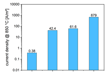
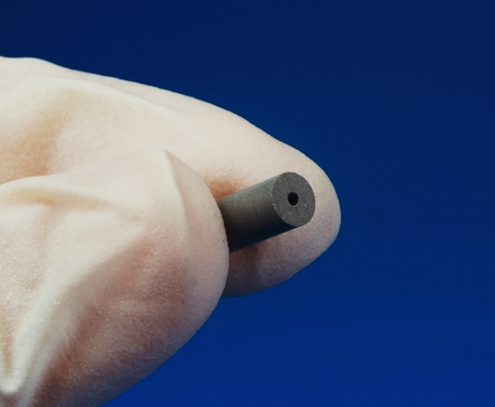
Figure 1: Improved current density of C12A7:e- by doping and contacting (left) and hollow cathode of C12A7:e- (right).

Highlights
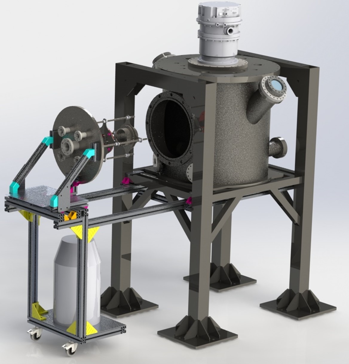
The first goal of this WP was to perform a 3000h endurance test on the ACFT using iodine as propellant. This goal has been successfully achieved. The second outcome of this activity is the evaluation of technical and safety procedures finalized to a proper operation of the vacuum simulator with iodine; this part of the WP is still ongoing.
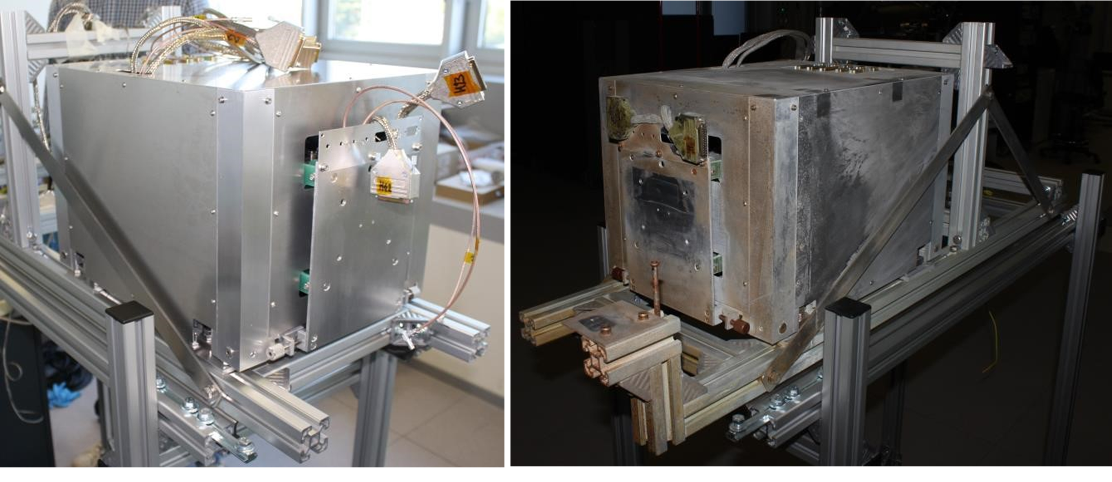
Significant Achievements
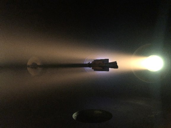
The design and dimensioning of a high vacuum pumping system capable of keeping the chamber pressure below the required level during the operation of the thruster fed with iodine have proven to be effective. Also, the customization of the simulator’s diagnostics, in terms of employed materials, showed no significant fault during the whole test. The thrust balance (see the included pictures), despite the huge amount of compounds deposited on the outer cover, was still fully operating at the end of the endurance test. Same result for the plasma probes installed in the rotating boom.
The main vessel of the vacuum simulator collected a huge amount of back-sputtered material; the present supposition, based on visual evaluation through the main vacuum chamber viewports, is that the high-energy iodine particles in the thruster’s plume reacted with the aluminum covering the chamber's internal walls, giving aluminum iodide as back-sputtered result material. This supposition is supported by chemical analysis of the compounds deposited on the thrust balance during the test. Further analysis will be possible only at the opening of the main vacuum chamber, at the end of the regeneration process.
The presence of considerable amounts of aluminum iodide as a secondary compound generated during the thruster operation raises the question of a rethinking of the surfaces used for the shielding of the chamber walls by the thruster plume.
The secondary equipment set up in the laboratory to safely handle the various phases of the test (safety glove box, iodine electrochemical sensors, chemical reagents to neutralize the iodine from the contaminated surfaces) has given excellent proof of effectiveness.
The vacuum simulator set-up for long-term testing with iodine is still open to improvement, in order to minimize the set-up contamination during the thruster operation. The last results coming from the completion of the vacuum chamber regeneration phase will allow this improvement.
The set-up of a fully equipped vacuum simulator, capable of operating for all the 3000h foreseen for the iodine-fed ACFT test has been amongst the most remarkable achievements of iFACT especially, considering all the challenges that the researchers faced due to the COVID-19 pandemic that was in progress during the whole system design, procurement, and integration phases.

Highlights
We have obtained a comprehensive understanding of the interaction of iodine with materials used on satellites. The deteriorating effect of iodine on various metal components is not critical for low iodine partial pressures even at long mission durations. It is predictable for high iodine partial pressures. Further, the sputtering effect of iodine is mainly physical and, thus, comparable to that of xenon. Chemical reactions of iodine in the sputtering process are of minor importance only.
Significant Achievements
In WP7, was investigated the interaction of different materials commonly used on satellites with iodine in the form of gas, plasma, and fast ions. The project researchers proved that the sputtering effect of iodine is equal to or less than the effect of xenon. Additionally, iodine in space-like low partial pressures does not damage most materials commonly used on satellites even considering extended mission durations.
The corrosive nature of iodine worries among others satellite manufacturers, test engineers, and investors. With WP7 findings, that iodine corrosion is much more predictable and much smaller in space-like conditions than expected, the deterrent effect of the corrosive nature of iodine gets less terrifying and helps to create a path for iodine-propelled satellite missions.
In WP7, the team of experts is most proud of their detailed investigations of chemical reactions between iodine and various metal components in a space-like environment. As a result, they are able to propose an experimental procedure to mimic the long-term effects of iodine in atmospheres characteristic for the space environment of iodine-fed electric thrusters.

Highlights
WP8 aimed at ensuring that the small electric propulsion subsystem meets the performance requirements through its integration on a CubeSat platform and through a campaign of tests of the integrated system. The tests have been performed in the Vacuum chamber.
Significant Achievements
In WP8 researchers have successfully tested the EnduroSat Power system with PPS with Xenon showing the that design of the smaller configuration of the propulsion system design by Airbus was performed according to the nanosatellite standards as per initial requirements.
As a result, a new propulsion system for nanosatellite can be released in the market. De-orbiting, debris avoidance, and station keeping are essential for keeping space sustainable and iFACT delivered important results towards making them possible. The successful test campaign paves the way for an in-orbit demonstration of the propulsion system while EnduroSat will consider its utilization in the standard 6U and 12U platforms.